
Earth resistance testing is an important part of verifying an earthing system. It confirms whether an earthing system can still carry excess electrical current safely into the ground, protecting people, machinery and electronic equipment from electrical faults and lightning strikes.
In this article, we’ll explain why earth resistance testing matters for mining sites, how soil resistivity influences earthing design, and how earth rod drilling and earth rod installation deliver a result that can be verified.
Earth Resistance Testing: What it Measures and Why it Matters
Earth resistance testing measures the resistance between an electrode or earthing system and the surrounding earth. The result helps assess earth potential rise during a fault, but it must be considered alongside fault current, return paths and protection operating times.
Soil resistivity is the main variable. It changes with moisture content, mineral composition, temperature and depth. Mining regions across Western Australia often combine dry, rocky surface layers with conductive zones deeper down, so readings taken near the surface can be misleading. A site that tests well after rain may perform poorly in the dry season.
A sound earth resistance testing program typically includes:
- Soil resistivity surveys before design, using the Wenner four-pin method, to identify lower resistivity layers and select rod depth and layout.
- Fall-of-potential testing on completed electrodes to confirm the installed resistance against the design target.
- Clamp-on or stakeless testing for routine inspection of existing earthing systems where driving test stakes is impractical.
- Periodic retesting at intervals set by the site electrical safety management plan, and after major construction, modification or a lightning event.
To ensure accuracy, test leads must be kept clear of buried services, and instruments should be calibrated and operated by competent personnel. Accurate results depend on method and conditions, so each reading should be recorded with the soil moisture conditions, date and test method. This record supports compliance and shows whether resistance is drifting over time, which is often the first sign of corrosion or a loose connection.
Electrical Systems and the Role of Earthing Systems on Mine Sites
Electrical systems on a mine site carry significant load. Processing plants, crushers, pumps, camps and remote power stations all depend on a stable electrical supply, and each connected structure needs a reliable connection to earth.
Earthing systems protect against three main hazards:
- Electrical faults. When insulation fails, excess electrical current needs a low-resistance route to ground so protective devices can disconnect the supply quickly.
- Lightning strikes. Open, elevated sites attract lightning. Effective dissipation of lightning current into the ground limits damage to machinery and reduces the risk of step and touch potentials around the structure.
- Electric shocks. A properly earthed system keeps exposed metalwork at a safe voltage, which is critical for personnel working around machinery and fixed plant.
The operational benefits are equally important. Sensitive electronic equipment such as control systems, instrumentation and communications gear is vulnerable to surges and unstable reference voltage. A high-resistance earth connection can cause nuisance tripping, equipment damage and unplanned downtime. Over time, those events add to maintenance costs and reduce plant reliability.
This is why earth resistance testing is treated as an essential part of electrical inspection. It gives site teams evidence that protection is working, supports compliance with applicable electrical standards and WA mining requirements, and helps many other large organisations in the resources sector demonstrate that risk is controlled.
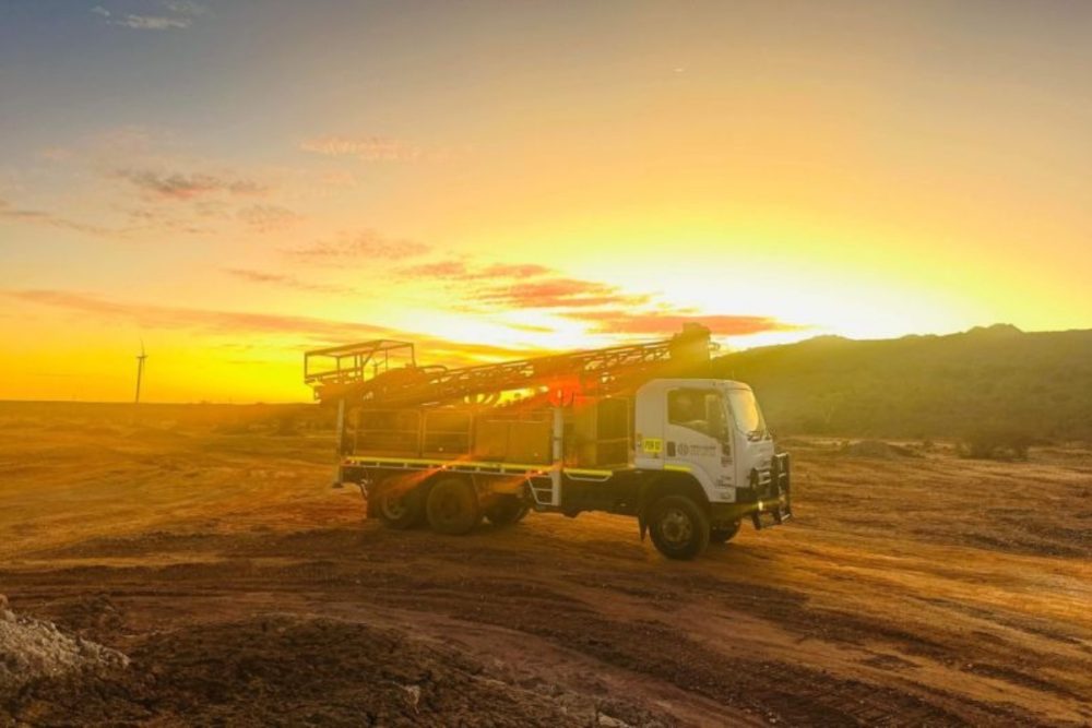
Earth Rod Drilling: Reaching Deep Earth Where Resistivity is Lower
Driving a rod by hand or with a hammer attachment is often enough on soft ground. On many mining sites, it’s not. Hard rock, cemented layers, laterite and dry surface soils limit how far a driven rod can penetrate, and shallow rods sit in the highest resistivity zone.
Earth rod drilling solves this by creating a hole to the required depth before the electrode is placed. A drilled hole allows the electrode to penetrate deeper into moist or more conductive material, where lower resistivity delivers a better result. It also supports a controlled installation, with the depth, diameter and backfill confirmed during the process.
The key advantages of drilling for earthing are:
- Depth. Deep earth electrodes reach stable, moisture-bearing ground that is less affected by seasonal drying.
- Lower resistance. Reaching lower resistivity layers can reduce the number of rods needed to meet the target value.
- Reduced footprint. Where multiple rods would otherwise be required across a wide area, a single deep electrode can limit surface disturbance and trenching.
- Predictable outcomes. Drilling logs and soil resistivity data inform the design, so the installed result is closer to the specified resistance.
Drilling also allows conductive backfill to be placed around the electrode. This improves contact with the surrounding ground and helps maintain performance as conditions change.
Earth Rod Installation and Copper Earth Rod Installation
An earth rod is only as reliable as its installation. Copper earth rod installation is widely specified for mining and construction sites because copper offers high conductivity and strong resistance to corrosion in most soil conditions. The materials selected must suit the soil chemistry, the expected load and the design life of the structure.
A typical earth rod installation process includes:
- Design and survey. Review soil resistivity data and confirm the target resistance, rod length and layout.
- Drilling. Drill to the specified depth, recording ground conditions as the hole is advanced.
- Rod placement. Install the copper earth rod and place conductive backfill to maintain full contact with the soil.
- Connection. Attach the grounding wire or cable using compression or exothermic connections suited to the environment. A poor connection is a common point of failure.
- Inspection. Check that all connected components are secure, corrosion-protected, and clearly identified.
- Testing. Complete earth resistance testing and record the result against the design value before the system is energised.
Testing after installation is not optional. A rod can be installed to specification and still return a high reading because of local ground conditions. If the value is above target, additional depth, multiple rods or improved backfill can be applied before handover.
Long-term reliability depends on maintaining the system. Routine inspection should look for corrosion at connection points, damaged cable, disturbed ground around the rod and any change in resistance compared with earlier readings. Early detection keeps repair work small and avoids the higher cost of a failed earthing system.
Drilling Services for Earthing Systems from Precision Drilling Australia
Precision Drilling Australia provides earthing and anode drilling as part of our specialist drilling services. Our crews work across remote and regional mining sites in Western Australia, the Northern Territory and South Australia, and we understand the access, logistics and safety requirements that come with them.
If you’re planning a new earthing system, upgrading an existing installation or investigating high earth resistance readings, get in touch to discuss your next project.
Frequently Asked Questions
The target value is set by the electrical design, the type of installation and the applicable standards, so it varies between a substation, a processing plant and a remote camp. Your electrical engineer or consultant should specify the required figure. Our role is to drill and install to the depth and layout that supports it.
Common causes include dry or rocky ground, a rod that is too short, rods spaced too closely, corroded or loose connections, and damaged grounding wire. Identifying the cause before adding more rods avoids unnecessary cost.
In many cases, yes. Clamp-on testing can measure resistance in a live earth loop without disconnecting the electrode. Where a full fall-of-potential test is required, the electrode is normally isolated first, and this should be planned with the site electrical team.
It depends on the soil profile. Where lower resistivity ground lies at depth, a single deep electrode often performs better and disturbs less surface area. Where resistivity is fairly uniform, multiple rods may suit the design. A soil resistivity survey shows which approach is more efficient.


